



Float Drain Traps
How they work, applications and maintenance

Float drain traps are mechanically automated valves used to drain liquids from piping systems without loss of process gas. They can also vent gases during system filling when installed upside-down.
The most common use is draining condensate from steam systems to maximize energy efficiency and prevent liquid slugs and wear on components. In steam systems they function as a type of steam trap. They are also widely used on compressed air systems (where condensate often contains compressor oil, scale and fines) and other industrial gas processes where condensation occurs.
When properly installed and maintained, float drain traps can operate 24/7 for a decade or longer before needing rebuild or replacement.
How Float Drain Traps Work
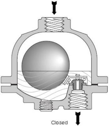
Liquid accumulates in the trap body and an internal float rises and lowers with the liquid level. A plunger-style valve is connected to the float by a lever and fulcrum. As the liquid level rises, the valve lifts off its seat and drains excess condensate. As the level falls, the float lowers and reseats the valve.
Internal components are non-magnetic stainless steel. The valve-to-seat interface is metal-to-metal (except the 1/8" orifice option, which can use a Viton grommet). Standard orifice sizes are 5/64", 3/32", 1/8" and 5/32". Larger orifices allow higher drainage rates; smaller orifices reduce cycle frequency and extend wear life.
A residual volume of fluid always remains in the trap, creating a barrier that prevents process gas from escaping during drainage.

Proper Installation
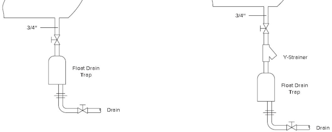
Install the float drain trap 6" below the separator (or vessel) drain. Add 1" of vertical drop for each 1" of horizontal run. The top of the trap should never be above the drain connection unless a balance line is added.
How to know if the trap is working: Visually confirm condensate is draining. If you can see, hear or smell process gas escaping, the valve is not seating properly. Install traps in accessible locations for observation and maintenance.
Maintenance
Locate traps where they can be observed and serviced. Use the blow-down plug periodically to clear scale and debris. Installing a Y-strainer upstream reduces blow-down frequency.
When service is required, remove the cap screws on the flanged body. All replaceable components are attached to the removable lower section.
Common Causes of Failure
- Valve/seat wear — most common failure, resulting in gas leakage. Accelerated by high cycle frequency or material incompatibility. Choose an orifice sized slightly larger than needed at your lowest operating pressure.
- Freezing — expansion can damage the float, lever, fulcrum or crack a cast iron body. Prevent with a 50W or 100W 120V heater inserted into the trap body.
- Over-pressurization — can damage the body, gasket or internal float assembly.
- Corrosion — residual liquid left in an idle trap can corrode the body. Drain the trap during long idle periods.
How to Repair Float Drain Traps
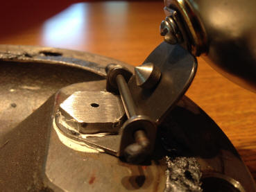
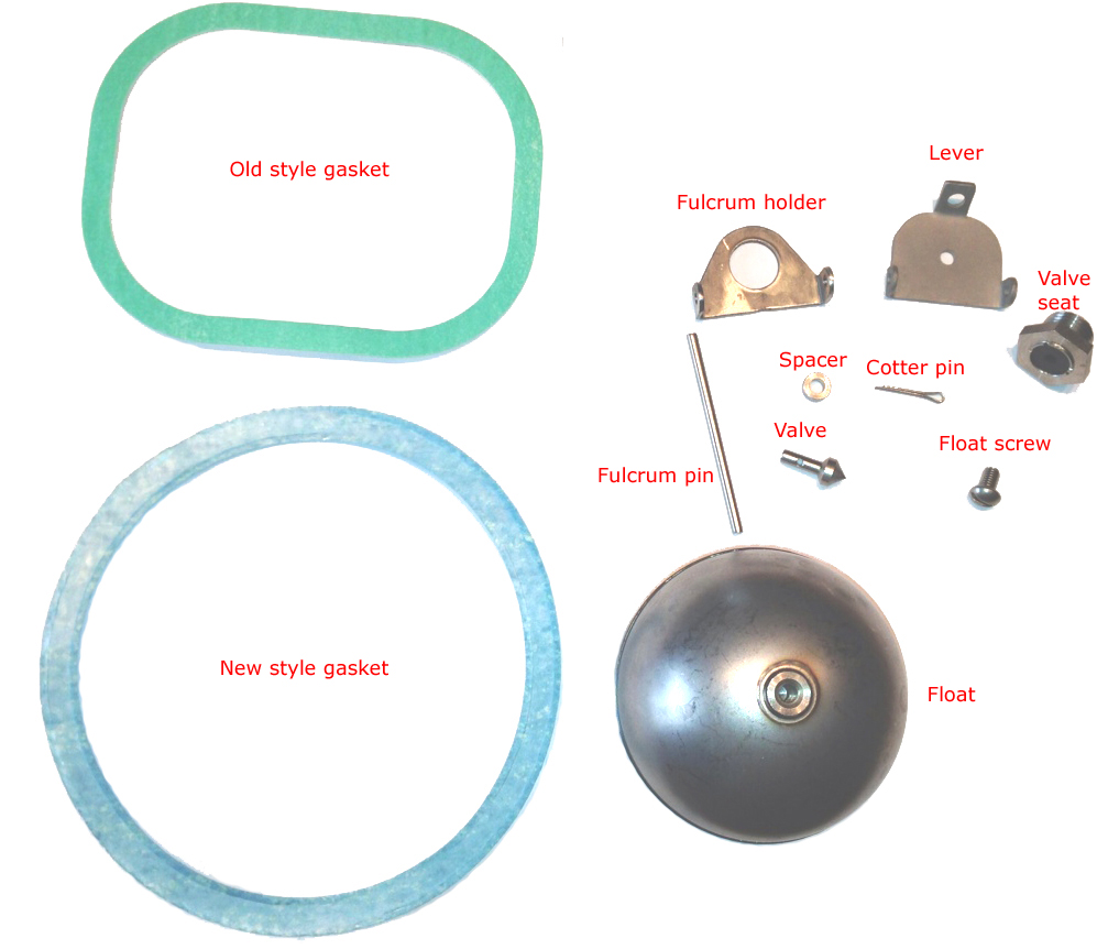
Repair kits contain all replaceable components. Remove the cap screws holding the lower half, then remove the fulcrum pin to free the float, lever and valve assembly. Replace the valve seat and, if needed, the valve (held by a cotter pin).
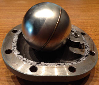
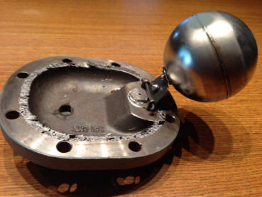
Kit vs. replacement: For cast iron traps the repair kit cost is often close to a new unit, so most customers simply replace them. For carbon steel and stainless steel traps the kit costs 35–50% of a new unit (saving >$1,000), making rebuild the better choice when lead times are long.
Problematic Applications
Float drain traps are not recommended for vacuum systems or liquids containing heavy oil, sludge or high concentrations of particles. These conditions impede proper operation. Contact us for alternate designs when larger drain orifices or different technologies are required.
Need help selecting or servicing a drain trap?
Request a Quote / Inquiry Formor call us: 908.362.9981