- The Company
- Articles
- Coalescer Gas Liquid Separator Designs
- Comparison of Centrifugal and Vane Style Gas Liquid Separators
- Design & Capabilities of Gas Liquid Separators
- Differences of a Knock-Out Drum and Centrifugal Gas-Liquid Separator
- Exhaust Head Design
- How float drain traps work, installation and maintenance
- How to identify a Wright-Ausin Separator
- How to Size a Moisture Separator
- Steam Traps vs. Steam Separators
- Efficiencies of Centrifugal Separators
- Understanding Sizing Factors For Gas/Liquid Separators
- Horizontal
- Vertical
- High Solids
- Coalescer
- Elements
- Exhaust Heads
- Float drain traps
- Liquid level gauges
- Sizing Calculators
- Inquiries
How to Identify Wright-Austin Gas/Liquid Separators
Call us at 908.362.9981 to speak with a sales engineer
Customers frequently ask for performance and maintenance information for their existing Wright-Austin separator. Sometimes this coincides with routine pipeline inspection and other times is related to application changes or perhaps a new application and they are considering “duplicating” an existing system. This article will explain how to identify most existing Wright-Austin gas/liquid separators; if the design criteria has changed (your application flow rate, gas composition, pressure, temperature and liquid load), then it will be necessary to re-evaluate the most applicable separator design. Since this is sometimes related to troubleshooting performance, we’ll touch on that subject also.
 History of Wright-Austin
Wright-Austin was established in 1894 in Detroit Michigan,
pioneering cyclone separator and steam trap designs. 102 years later
(1996) they were acquired by Hayward Filtration. At that time
Hayward had both alloy and non-alloy pipeline strainer products and
the centrifugal separators were considered an expansion of their
industrial filtration products.
Manufacturing was transferred to Hayward in New Jersey and key
personnel were tasked with training of Hayward employees. In
particular, one gentlemen (who worked as an engineer for
Wright-Austin for 22 years prior to becoming the plant manager and
vice president during the last 6 years before the acquisition by
Hayward) made weekly trips to New Jersey for 6-8 months to ensure a
smooth transition.
Nine years after acquiring Wright-Austin, Hayward divested of the
alloy filtration products (including the gas/liquid separator
products) and sold them to Eaton Hydraulics, Filtration Division.
Records Nightmare
Separators manufactured under Eaton are easily looked-up by serial
number and the design criteria is usually associated with its
drawing. Separators manufactured under Hayward are not as easily
looked-up; for whatever reason those database files were lost or not
transferred to Eaton. The Wright-Austin separators fabricated in
Michigan are mostly documented on microfiche with the physical
documents stored off-site, so obtaining the information on those
vintage units is often possible but might require one or more weeks
to obtain.
Field Identification
Sometimes the nameplate is missing or covered-up in insulation so we
cannot be sure when it was fabricated or by whom, in such a case
here’s how we suggest identifying your separator:
1. Method and Material of Construction
If the separator is installed on a 5” or smaller pipeline and is
made from a casting, it is very likely a standard cast iron type T
separator as illustrated in a
drawing link from the cast T webpage.
These are commonly used in both steam and compressed air systems and
since they are castings, they are not modifiable, so the drawings
above provide key dimensions you can double-check against yours to
figure-out which size you have – and from there its performance. If
not a casting, verify material and design.

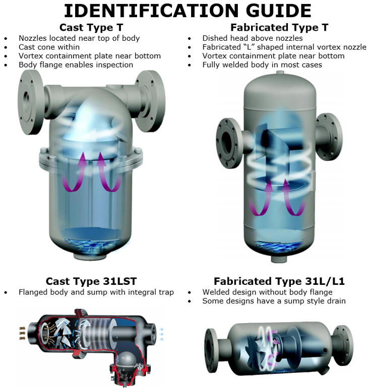
2. Design or “Type”
There are two basic configurations of centrifugal separators, a
horizontal barrel style
and a
T style. The barrel style may be
installed in a section of pipeline that is either horizontal,
vertical or combination of each whereas the T style must be
installed within a horizontal section of piping. Once the shape is
matched to the various types of separators offered, we can provide
the applicable drawing of the standard design for that type of
separator to determine the approximate size.

Fabricated separators are often customized; the most common
customizations include reduced nozzle size, additional nozzles,
inspection ports, liquid level gauge connections and corrosion
allowance. When the dimensions of the standard product do not
directly correspond to your separator, note which dimensions differ.
It is usually the inlet-to-outlet and body diameter dimensions and
this is often related to reduced (non-standard) nozzles.
3. 
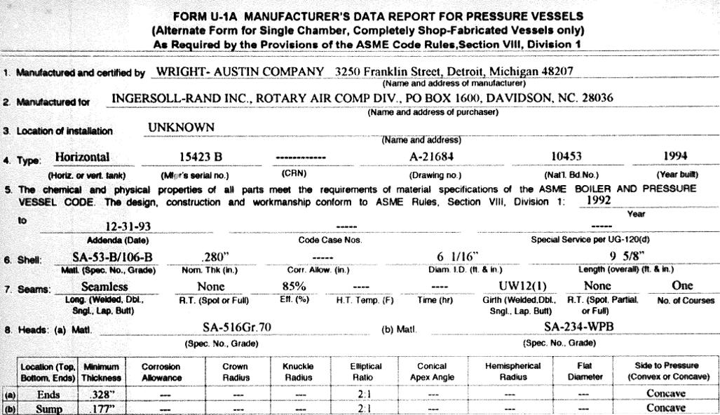
ASME code stamped separators are registered with the National Board of Boiler and Pressure Vessel Inspectors (NBBI) and the registration papers provide some basic information about the separator:
a. Manufacturer
b. Type
c. Serial #
d. Drawing #
e. Year built
f. Length & Diameter
g. Material
h. Wall thickness of body & heads
i. Max/Min temperature and pressure
j. NDT (most commonly hydrostatic test results)
k. Description of all ports/nozzles
You can contact the National Board to purchase a copy of the report on file; you need to submit the original manufacturers name and the national board number. If you do not have the documentation referencing the national board number, you can try submitting the manufacturers serial number and year built (on nameplate).

If the nameplate is missing and there’s no documentation referencing the national board or manufacturers information, then you need to rely on #1 and #2 above.
Purpose of Identification and Troubleshooting
If you are just trying to evaluate performance or determine if your
unit requires maintenance, identification by dimensions should be
sufficient. All non-coalescing centrifugal separator designs remove
entrained droplets and particles larger than 10 microns with 99%
efficiency. There are no internal components to service or replace,
it is a fully welded (or cast) vessel considered both self-cleaning
and maintenance free. If your process conditions have not changed
and the performance of your separator has not changed (increased
liquid downstream of the separator) then it is likely fine. If the
separator has been sitting idle with residual liquid inside, a
visual inspection through the nozzles and perhaps ultrasonic
inspection of wall thickness should be performed to determine if
corrosion is severe.
If your performance has changed, usually attributed to increased
liquid downstream of the separator, then first double-check the
design criteria for your application – has it changed? An increase
in flow rate or liquid into the system may overwhelm your existing
separator. Also, check your float drain trap or valve system for
draining the liquid; if it is not functioning properly liquid might
become re-entrained within the separator.
Please call us at 908.362.9981
or email support@wright-austin.com
for immediate assistance with your specific application. We will
assist you with identification of your existing separator and verify
it is appropriate for your current design criteria.


